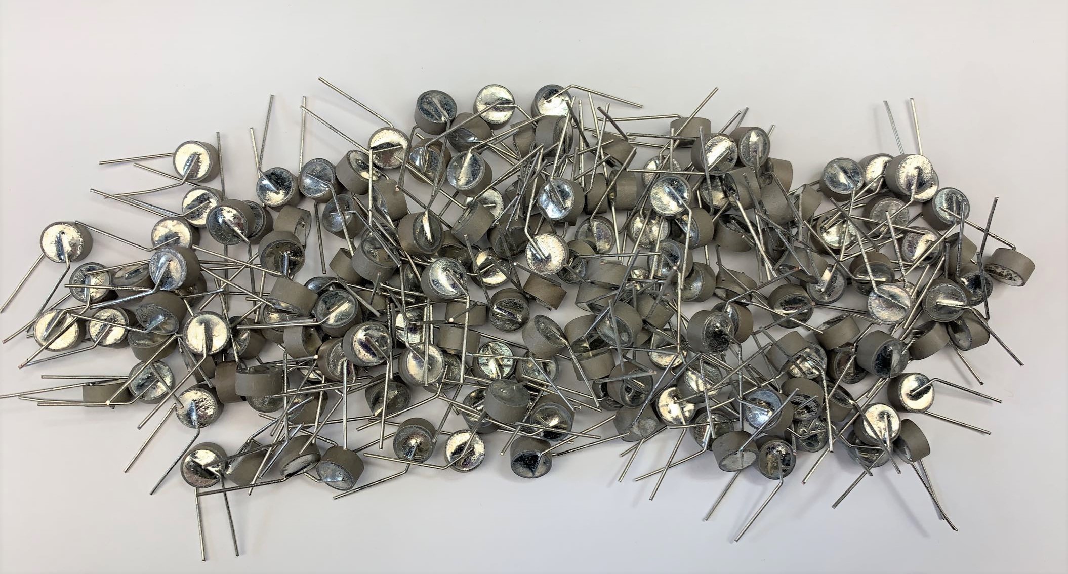
 When designing a PTC thermistor for use as an over-current protector, you should first determine the following information:
- Maximum steady-state voltage across the PTC when it is the current limiting mode.
- Minimum and maximum ambient temperature.
- Maximum normal current and minimum fault current.
For a PTC thermistor, values for the minimum current that the part will switch (Ims) and for the maximum current that the part will not switch (Ins) can be calculated. These values are dependent upon the ambient temperature, the resistance value of the PTC, the dissipation factor (o), as well as the switch temperature (Ts). The values listed in the MS catalog for Ims and Ins are based on a minimum ambient temperature of 0°C and a maximum ambient temperature of 50°C. If these ambient conditions are not desired then the following equations can be used to calculate the values.
Minimum Must Switch Current
Maximum No-Switch Current
For example, for a small transformer that you would like to protect, you have determined the following:
Vapp = 24 volts app
Normal current = 80mA
Fault current = 300mA
Tamin = 20°C
Tamax = 60 °C
For this application, we will need a part that is rated for at least 24 volts and can carry 80mA of current at 60°C and will switch with less than 300mA through it at 20 °C. Looking through the parts rated for 50V we find MS Part Number P3006C120X201F, which is a 20Q part. Going through the requirements we find that:
Therefore, MS type P3006C120X201F will provide adequate protection for the 24-volt transformer.
The PTCs listed in the standard over-current protector datasheet are often modified to fit each individual application. By varying the resistance at 25°C, the switch temperature (Ts), the type of lead wire, or the part size, MS can customize a PTC to meet your requirements.
As noted previously, PTCs cannot be connected in series to obtain higher voltage ratings. One device would heat more rapidly than the others and prevent the other PTCs from switching. However, PTCs can be connected in parallel to increase their current rating.

