Design Considerations for Standard Heaters:
When selecting a PTC, you should consider the following factors:
- Thermal Connections
- Switch Temperature (Ts)
- Resistance at 25 °C (R25)
- Surface Area
- Maximum Voltage (Vmax)
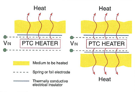
Ceramic PTC heaters are usually most efficient when they are flat and thin and have a smooth surface finish. For a PTC to operate as a heater, it must have a way to dissipate its heat to the medium, either by convection (air or liquid flow) or conduction. One common method is to use a spring contact as both the electrical and mechanical connection (See Figure 13). One advantage of this "clamping" technique is that it allows stress-free thermal expansion. Other techniques involve using electrically conductive epoxies or solder joints to connect the PTC to the heat spreader.
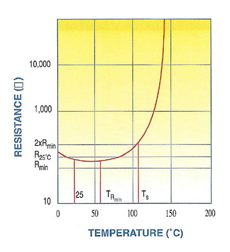
The switch temperature (Ts in Figure 12) is very important because, in most heater applications, the maximum surface temperature of the PTC is just a few degrees above its switch temperature. Thus, the maximum temperature of the medium to be heated is directly related to the switch temperature Ts of the PTC.
 Figure 13
 Figure 12
The R25 of the PTC heater is typically not the most important design factor. It should not be so low that it causes inrush current problems, but not so high that there is not enough power available to heat the PTC to its switched condition. The PTC cold resistance will, however, influence the heat-up rate of the medium since a lower resistance allows for higher initial I2R heating.
The surface area of the PTC heater influences the heat-up and cool-down rates of the medium as well as the power dissipated. Multiple PTCs are often used in heater design to obtain the desired results. As with any PTC thermistor application, the heater design should not exceed the maximum recommended voltage ratings. The maximum voltage (Vmax) specified on the MS data sheets is for DC or 60Hz AC only.

